Interfacing External Hardware to your FPGA board
Here are two suggestions:
Most boards have 40 Pin header connectors but double check first. Make a short ribbon cable using a 40 Pin .1 inch female header and a 40 Pin DIP plug at the other end. The DIP plug can plug into a standard .1 inch protoboard and the header can plug into the FPGA board. You can then add external hardware on the protoboard. Be sure to connect the GND on the protoboard to the FPGA boards GND. If the protoboard has it's own 5V power supply, do not connect it's 5V output to the FPGA board. Also be sure to double check if the FPGA header uses 5V or 3.3V logic levels (5V logic connected to 3.3V logic does not work unless a special IC is used that limits the voltage levels - double check the FPGA board's manual and/or schematic).
Use ExpressPCB's free CAD software
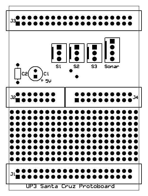
to make your own custom PCB. A blank PCB board design with the header and
power connections that plugs into the expansion connector on the Altera
UP3 is available
here
for this software. You will need to add traces to connect your new components.
Making several boards on one order can get the per board price under $20.
Be sure to add power supply decoupling capacitors to the board to limit
noise. Use a large value capacitor, 10-100uf, connected in parallel with
a small value ,.1 uf (do not just use one!)
UP3 Protoboard Layout