VIDEO SLOT MACHINE

Prepared for:
 
Ralph A. Carestia
Oregon Institute of Technology
Computer Systems Engineering Technology Department
 
 
Prepared by:
 
Edward C. Hennessy
ENGT 507 
 
 
Date:
 
November 7, 1997


INTRODUCTION

This project creates a video slot machine game using the EPF10K20 FPGA on the Altera UP1 Education Board.  The design is based off an earlier project, also implemented in an FPGA, but without video.


TECHNICAL ANALYSIS

The technical analysis examines the system inputs, outputs, and behavior to sketch out a description of the system.  The description is used as a rough outline while creating the source code.

INPUTS

The slot machine requires two inputs: a momentary pushbutton to change the bet and a momentary pushbutton to spin the wheels.  The pushbutton to change the bet must only be active at the idle state, so the player cannot change the bet during the spin.  The pushbutton to spin the wheels must be released and pressed again to play again.  In the earlier model, people left a scotch tape dispenser or rubber band on the wheel, making the game play continuously.

OUTPUTS

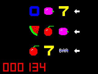
The only output, a video display, shows the three wheels, the active paylines, and the player's credits.  The graphic below closely approximates the slot machine's actual video display.  The white arrows show which paylines are active.
 
 
The game must generate all video signals for the VGA monitor.  Since the three color signals are all digital (the gun is either on or off), this format limits the game to eight colors.

BEHAVIOR

This slot machine behaves similar to the ones found in Las Vegas or Reno.  The core of slot machine is a state machine with 4 sequential steps.  Each of these steps entails more steps, and the project is designed as a heirarchial state machine.  The following list shows the 4 sequential steps at the top level of the machine: 
  1. Wait for the spin button to be pushed.
  2. Deduct the bet.
  3. Spin the wheels.
  4. Payout the value for winning combinations.
Each step in the above list is composed of smaller steps, not discussed here, but found in the code (Appendix B).

The following table shows the value of payouts for each winning combination, designed to give a house PC of 88.9%.  The odds of winning are controlled by the number of symbols in each wheel. (Appendix F)
 

Symbols Description Payout
Cherries 3
Cherries with bars (any combination) 3
Plums 6
Plums with bars (any combination) 6
Watermelons 12
Watermelons with bars (any combination) 12
OIT Letters 25
Bars 50
Sevens 100
Diamonds 500
Developer's Initials 1000


TECHNICAL DESCRIPTION

The top level of the project (vslots.gdf) divides the video slot machine into two functionally separate subdesigns: the slot machine game and the video display controller.  The display type can be changed with minimal modifications to slot machine game.  The slot machine game, however, anticipates the symbol height in scan lines in the wheel logic.  Although the two subdesign's sequential logic is completely separate, the slot machine uses the display controller's vertical sync output for the clock input.  This way, all changes in the slot machine's outputs occur on the positive edge of the vertical sync.  All changes in the slot machine outputs occur during vertical retrace, eliminating display flicker.

SLOT MACHINE

The slot machine (slots.tdf) logic uses a heirarchial state machine to implement behavior.  At the top level, the machine is either waiting, deducting, spinning, or paying.  Control signals from this state machine feed the bet logic, credit logic, payout logic, and wheel logic.  Each one of these subdesigns contain a state machine to define their behavior, and when finished with the their operation, return a signal to the slot machine logic to change to the next state.

Bet Logic

The bet logic (bet.tdf) controls how many paylines are active.  The player can cycle through the active payline combinations with one pushbutton.  The bet logic will not allow the player to bet more credits than they have, and the bet logic will also reduce the bet if the player runs low on credits.  Both the player and bet logic cannot change the bets during the game.  An enable signal to the bet logic, only active in the waiting state, prevents the bet from changing during the game.

Credit Logic

The credit logic (credit.tdf) uses a six decade up/down BCD counter to store the player's credits. The counter counts down during bets and up during payouts.  The credit logic contains a state machine and a binary counter to contain the transaction amount.  The binary counter will be loaded with the transaction value and the state machine will keep both counters running until the value is transferred from the counter to the player's credits.

Payout Logic

The payout logic (payout.tdf) calculates the payout values for the symbol combinations on each line.  An internal state machine iterates from the top payline to bottom payline, and if the payline is enabled, calculates the payout for the line.  Losing combinations produce a payout value of zero.  For each line, the payout value is fed to the credit logic to accrue credits for the player.  The payout logic will wait for the credit logic to signal transaction complete (PAID) before continuing with the next payline.

Wheel Logic

The wheel logic (wheel.tdf) controls the position of the three wheels.  The slot machine sends the command to spin the wheels, and when done, the wheel logic will respond when the wheels have all stopped.  The logic will spin each wheel a random amount to jumble the symbol combinations.  The wheel logic will also reduce the speed of the wheels to give the impression of a gradual slow-down.  The wheels will continue to spin one scan line per frame until the symbols line up centered on each payline.

DISPLAY CONTROLLER

The display controller (dispctrl.tdf) takes the outputs from the slot machine and generates the video signals required to produce the game's display.  The display controller consists of a video sync generator, and separate modules to create each of the three display elements.  The three display elements include the wheel display, credit display, and the payline arrows.  Any transition on the inputs immediately reflect on the outputs, wherever the raster may be.  To eliminate flicker, the inputs should be changed during vertical retrace. 

Video Waveform Generator

The video waveform generator (vidwavg.tdf) generates video syncs, and signals to control active regions.  There are three separate active regions, one each for the numeric display, wheel display, and the payline arrows.  Each active region is defined by a horizontal active and a vertical active signal.  When both signals are asserted, the raster will be within the active region for the particular display element.  The graphic below shows the active regions and the corresponding display elements on the actual screen.


Numeric Display

The numeric display (numdisp.tdf) mimics six, seven segment displays for the player's credits.  To create a seven segment display, the controlling logic uses two waveform generators:  one generator for horizontal timing and one for vertical timing.  Each waveform generator provides an active signal for each segment: A through G.  When both horizontal and vertical signals are active, the raster should be within the segment on the video display.  If the segment is illuminated on the current digit, then the red gun is activated to paint the segment.

Wheel Display

The wheel display (wheeld.tdf) produces the three graphic wheels in the center of the display.  Each scan line, the wheel display loads a shift register with graphic data and shifts the data out as the raster moves horizontally.  This process is repeated three times each scan line, once for each wheel.  Vertically, the wheel display counts each scan line, and this determines which scan line of graphic data to retrieve from ROM.

Payline Arrows

The payline arrow display (linedisp.tdf) produces the white arrows to indicate the active paylines.  The payline arrows use a scan line modulo counter to produce the three arrows.  When an arrow is active, data is loaded into a shift register and shifted out as the raster moves horizontally, producing the arrow pattern.  The modulo counter determines both the location of the arrow and which scan line of graphics data to load the shift register with.


CONCLUSION

This slot machine made an excellent quarter project.  The UP1 education board relieves the burden of wire-wrapping, allowing the project concentration to be on AHDL development.  Also, the ByteBlaster allowed the compiled code to be tested quickly.  With a certain level of functionality, the project could be tested by uploading and running the design, as opposed to using the simulator.  This project could not have been completed within the quarter without both these tools to speed up the development process.